Geutebrück
Introduction
This guide describes the steps required to integrate Geutebrück with the GCX-ONE platform. Geutebrück is a professional Video Management System (VMS) that provides recording, live viewing, video playback, and event/alarm management for connected cameras and security hardware. GCX-ONE integrates directly with Geutebrück, allowing streams and events from G-Core servers to appear alongside other devices in the GCX-ONE platform.
| Web API Interface (HTTPS) | Port 13333 |
|---|---|
| RTSP Streaming | Port 554 |
Applications
• G-Set: system configuration client — used to add hardware, configure media channels, and set up event and behaviour rules.
• G-View: operator client for live viewing, playback, and event monitoring.
• GPLC Simulator: PLC test simulator for I/O and manual event workflows, used during testing.
Geutebrück Configuration
A. Starting G-Core
G-Core is the server component of Geutebrück. It must be running before G-Set or G-View can connect. Start it from the Command Prompt as Administrator:
- Open Command Prompt as Administrator.
- Navigate to the G-Core installation folder: cd %gngpath%
- Stop any running instance: GCoreServer.exe stop
- Start G-Core — use Demo mode for testing (GCoreServer.exe demo) or Licensed mode for production (GCoreServer.exe start).
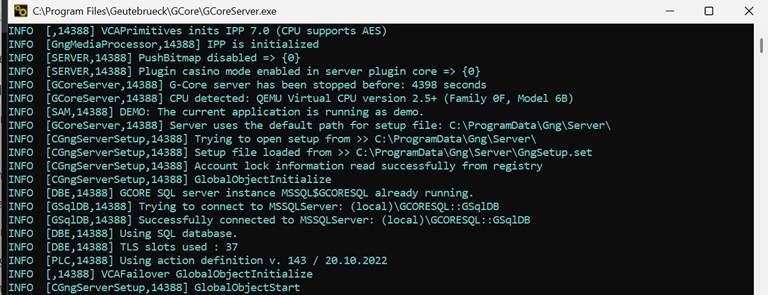
Figure 1: G-Core running in Demo mode — server started and connected to the SQL database.
B. Connecting G-Set to the Server
Once G-Core is running, launch the G-Set client and connect to the server using the Connection Wizard.
- Open G-Set. Click Connection Wizard on the main screen.
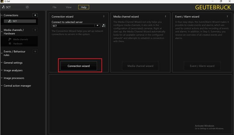
Figure 2: G-Set main screen — click Connection Wizard to begin.
- Enter the Connection name, Host name (G-Core server IP), Username, and Password. Default credentials: username = sysadmin, password = masterkey. Click Ping Host and Check Connection to verify, then click OK.
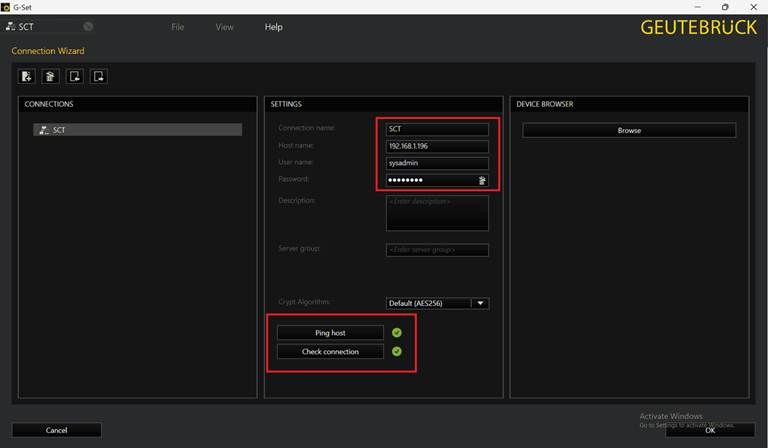
Figure 3: Connection Wizard form — enter host details and verify connectivity before saving.
- In the Connections panel, right-click the connection and select Connect.
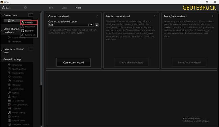
Figure 4: Right-click the connection name and select Connect to establish the session.
C. Adding Hardware (IP Camera)
Hardware in G-Set represents the physical camera device. Each camera is added as an IP-Camera plugin module.
- In the left panel, expand Media channels / Hardware and click Hardware.
- In the Hardware module list, right-click and select Add.
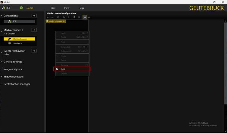
Figure 5: Hardware module list — right-click and select Add.
- In the Add hardware module dialog, select IP-Camera Plugin
and click Add. 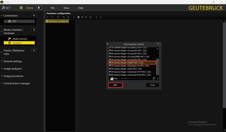
Figure 6: Select IP-Camera Plugin
- Configure the hardware module and click Save:
| Name | Descriptive name for the module (e.g., SCT-Entrance) |
|---|---|
| Hostname | IP address of the camera |
| Username | Camera login username |
| Password | Camera login password |
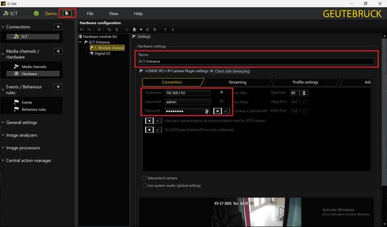
Figure 7: Hardware configuration panel — enter camera name, hostname, and credentials.
D. Adding a Sensor (Media Channel)
A media channel in G-Set is what GCXONE recognises as a sensor. It links a video stream from a hardware module to the GCXONE device.
- In the left panel, click Media channels under Media channels / Hardware.
- Right-click in the list and select Add.
Figure 8: Media channel list — right-click and select Add.
- In the Module channels dialog, select the hardware module you just created and click Add.
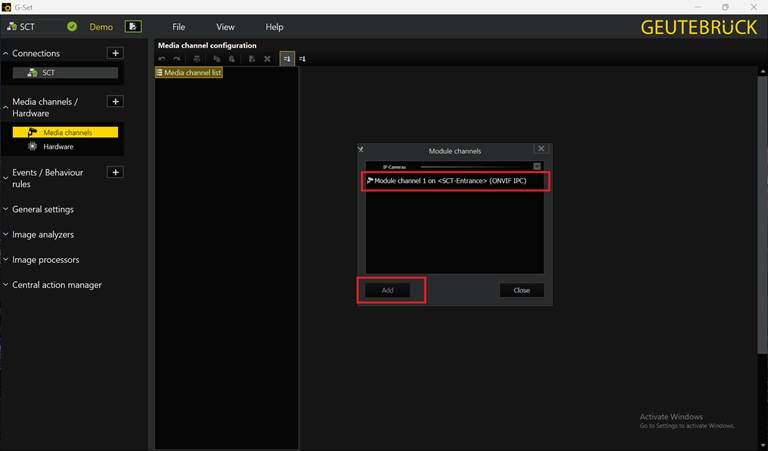
Figure 9: Module channels dialog — select the hardware module (e.g., Module channel 1 on
- Enter the channel details and click Save:
| Name | e.g., SCT-Entrance |
|---|---|
| Description | e.g., This is entrance camera |
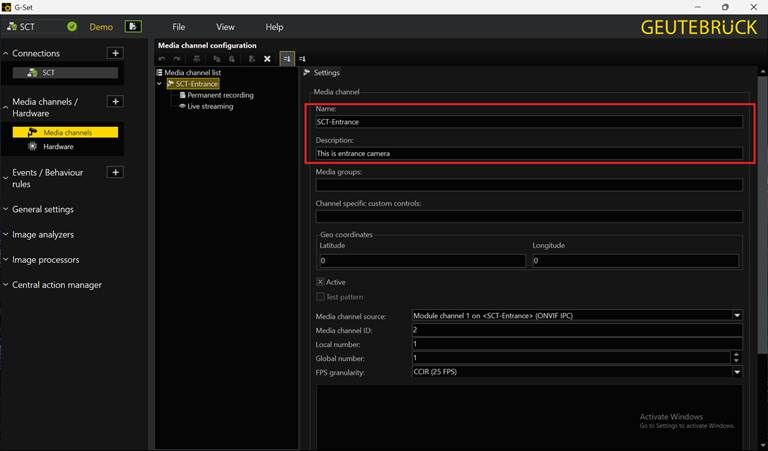
Figure 10: Media channel settings — enter the channel name and description.
- Select the channel in the tree, open Permanent recording, enable it, and click Save. The sensor is now added and linked.
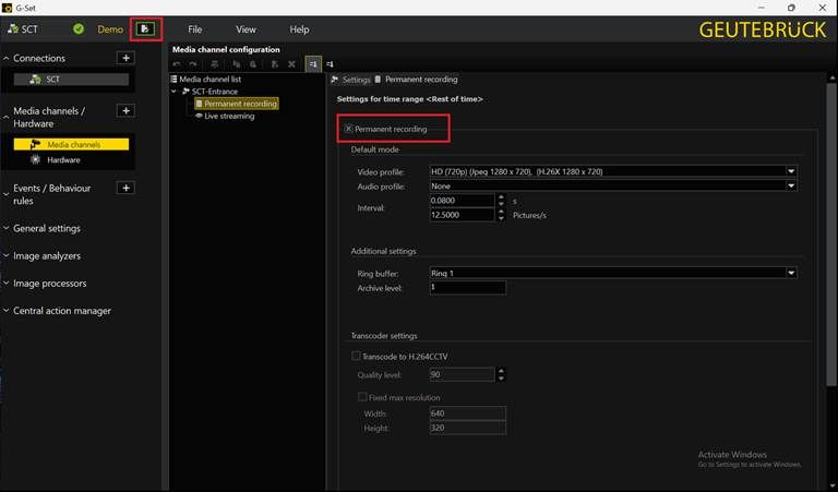
Figure 11: Permanent recording enabled for the media channel.
G-View Application
G-View is the operator client used to watch live feeds, review recorded footage, and monitor events.
- Launch G-View. In the Video servers panel, right-click the server name and select Connect.
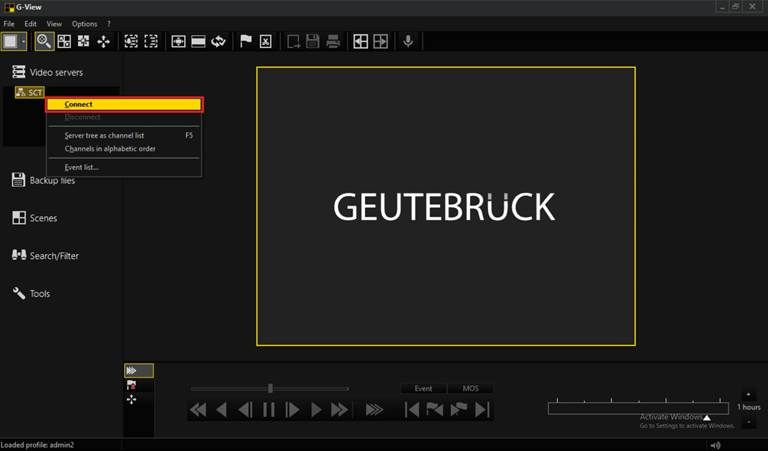
Figure 12: G-View — right-click the server and select Connect.
-
Expand the server tree. Double-click a media channel to open its live stream.
-
Use the playback controls and the Event / MOS timeline tabs to review recorded footage and jump to event markers.
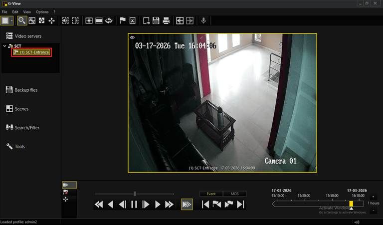
Figure 13: G-View live feed — SCT-Entrance channel streaming with timeline visible.
Geutebrück Config Guide with GCX-ONE
A. Add a Geutebrück Device
With the custom property in place, register the Geutebrück G-Core server as a device under the target site.
- Navigate to the target site in the Configuration app and open the Devices tab. Click Add.
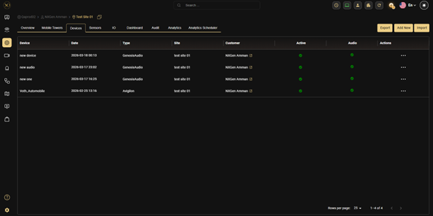
Figure 14: Site Devices tab — click Add to register a new Geutebrück device.
- Fill in the new device form:
| Device Name | e.g., Geutebrueck Camera - Gate A |
|---|---|
| Device Type | Geutebrueck |
| IP Address / Host | IP address of the G-Core server |
| Https Port | 13333 (default) |
| Username | G-Core login username |
| Password | G-Core login password |
| Server Port | 13333 (default) |
| Control Port | 13333 (default) |
| RTSP Port | 554 (default) |
| Event Polling | Enable |
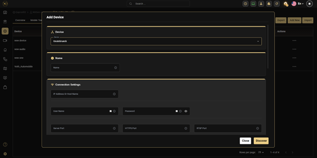
Figure 15: New Device form — select Geutebrueck as the device type and fill in the server connection details.
- Click Save & Verify to confirm GCXONE can reach the device and receive stream data.
B. Verify the Live Stream in GCXONE
Once saved, sensors from G-Set appear under the device in GCXONE. Open any sensor in the Video Viewer to confirm the live stream is active.
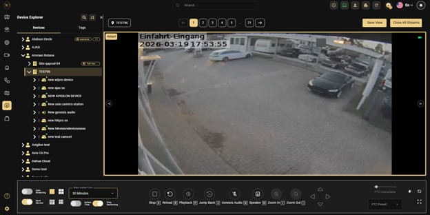
Figure 16: GCXONE Video Viewer — live stream from the Geutebrück-connected camera confirmed.
Event Rule Configuration in G-Set
Event rules define what triggers an alarm, how the system responds, what is recorded, and how the alarm appears in G-View and GCXONE. The Event/Alarm Wizard guides you through five steps.
To open the wizard: in G-Set navigate to Events / Behaviour Rules → Events, right-click in the event list and select Add.
Step 1 — Event Settings
Enter the event name, configure timing, and set database storage options.
•Event name: enter a descriptive name (e.g., VMD event).
•Retrigger mode: set to Retrigger to allow the event to restart while already active.
•Store to database: ensure On start and On stop are enabled so events appear in logs.
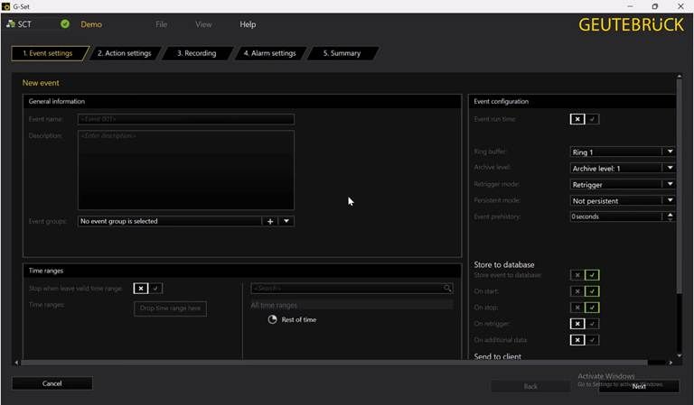
Figure 17: Step 1 — Event Settings. Configure the event name, ring buffer, retrigger mode, and database logging.
Step 2 — Action Settings
Define which alarm actions start and stop the event by dragging items from the Action list into the Start by and Stop by zones.
•Start by: G-Tect/VMD alarm — triggers the event when motion is detected.
•Stop by: G-Tect/VMD alarm finished — ends the event when motion stops.
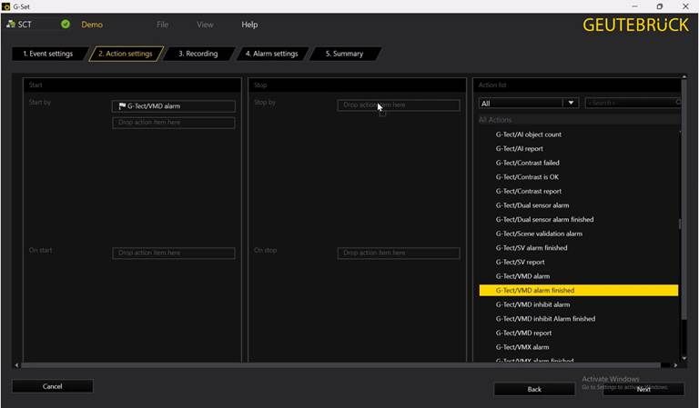
Figure 18: Step 2 — Action Settings. G-Tect/VMD alarm assigned as the Start action. The Action list shows all available triggers.
Step 3 — Recording Settings
Assign the media channels to record when the event fires by dragging them from the channel list into the Recording channels drop zone.
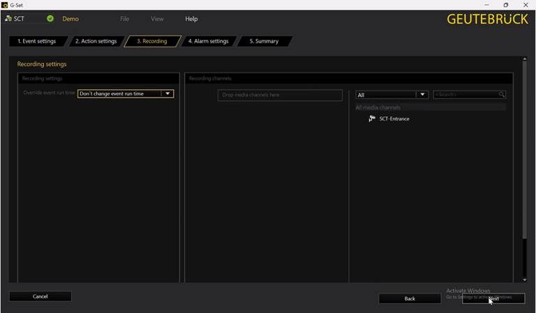
Figure 19: Step 3 — Recording Settings. SCT-Entrance is available in the media channels list.
Step 4 — Alarm Settings
Configure the alarm that appears in G-View and GCXONE when the event fires.
•Alarm name: e.g., test or VMD alarm.
•Alarm priority: High, Medium, or Low.
•Media channels: drag the camera channel so the alarm opens its feed automatically.
•Default alarm scene: enable to display the camera when the alarm is acknowledged.
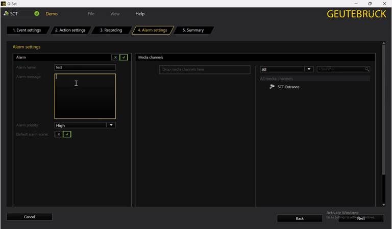
Figure 20: Step 4 — Alarm Settings. Alarm name, priority, and associated media channel are configured.
Step 5 — Summary
Review the complete configuration in one table, then click Save & Finish to commit the event rule.
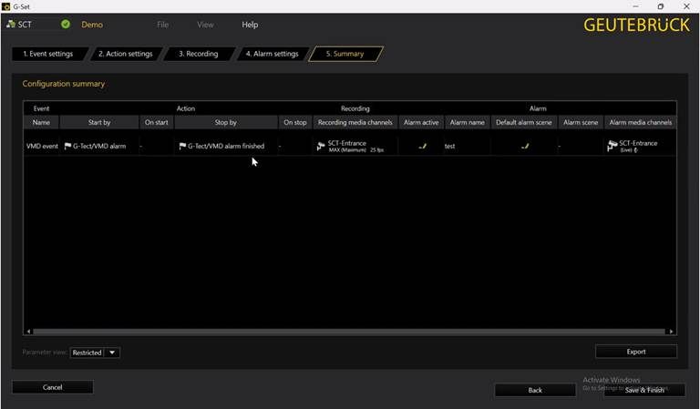
Figure 21: Step 5 — Configuration Summary. VMD event with G-Tect/VMD alarm trigger, SCT-Entrance recording, and test alarm confirmed.
Reviewing the Event Configuration
After saving, clicking an event in the G-Set Events tree opens its full configuration — including the event tree, recording task, media channels, and playback profile.
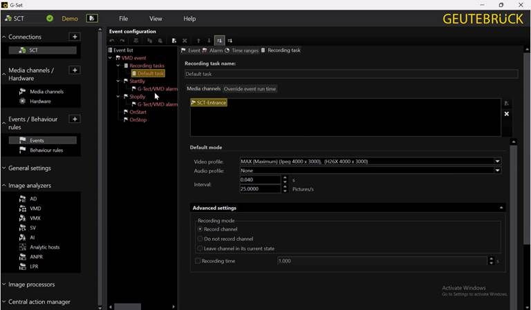
Figure 22: Event configuration detail — VMD event tree showing Recording tasks, StartBy, StopBy, and recording profile at 25 fps on SCT-Entrance.
Once events are saved in G-Set, they are automatically transmitted to GCXONE via the device integration. No additional configuration is required in GCXONE to receive Geutebrück events — they appear in the GCXONE event log alongside other device events.
Troubleshooting
Viewing Event Logs in G-View
All triggered events are logged in the G-View Event list. A populated log confirms the device is online and events are being captured correctly.
- Open G-View and connect to the server.
- In the top menu bar, click View then select Event list.
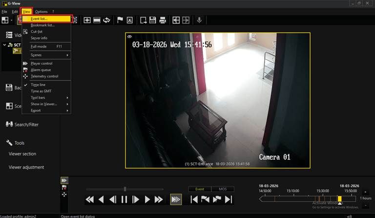
Figure 23: G-View — View menu with Event list highlighted.
- The Event list opens. Each entry shows:
| Start time | Timestamp when the event was triggered |
|---|---|
| Event name | Name assigned in Step 1 of the Event Wizard |
| Stop time | Timestamp when the event ended |
| Text / Description | Description text set in the event configuration |
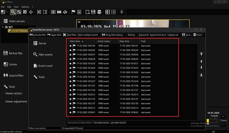
Figure 24: G-View Event list — VMD events logged with start time, stop time, event name, and description. A populated log confirms end-to-end integration.
A populated event log confirms that events configured in G-Set are successfully captured, stored, and visible in G-View — validating the complete Geutebrück integration from device to GCXONE.
For technical support or integration assistance, contact NXGEN Technology AG through the GCXONE support portal.t