Teltonika
Introduction
Teltonika IoT routers serve as the connectivity backbone for GCXONE Tower Monitoring, providing real-time cellular status, GPS tracking, I/O state changes, and signal quality data from remote tower sites. This guide walks through the complete onboarding process for a Teltonika IoT router — from adding the device in GCXONE and entering the required credentials, to configuring alarm rules for network loss, geo-fencing, SIM data usage, and jammer detection.
What Teltonika Devices Monitor
Once connected to GCXONE, Teltonika routers continuously report the following categories of telemetry:
- Network connectivity status and signal quality (RSRQ, RSRP)
- SIM card data usage against configured monthly limits
- Physical input/output (I/O) port state changes — digital, analog, isolated, relay
- GPS position relative to the assigned site boundary (geo-fencing)
- Jammer detection based on sudden signal degradation patterns
Teltonika handles communication, GPS tracking, and edge telemetry routing for the tower. This makes it the backbone of connectivity monitoring — without it, GCXONE cannot detect network outages, signal interference, or unauthorized device movement.
Prerequisites
Before starting device onboarding, ensure the following information and access are available:
| Requirement | Details |
|---|---|
| GCXONE Access | Admin or Operator role with Configuration module access |
| Device Credentials | Administrative username and password for the Teltonika router |
| IP Address | Public or VPN-accessible IP address of the Teltonika device |
| Serial Number | The unique hardware serial number of the router |
| Control Port | HTTP port used for device communication (e.g., 80) |
| Site Created | The site this device will be assigned to must already exist in GCXONE |
Ensure the Teltonika router is online, reachable from the GCXONE server (direct IP or via VPN), and that the administrative credentials provided have full API access.
Teltonika Config Guide with GCX-ONE
Follow these steps to add a Teltonika IoT router to GCXONE. The device will be registered under an existing site and begin reporting telemetry immediately after configuration.
Step 1 — Navigate to the Site
In GCXONE, navigate to the Site where the Teltonika device is physically installed. This is the parent entity under which the device will be registered.
- Go to Configuration → Sites
- Locate and open the target site
- Click Edit to open the site's configuration panel
Step 2 — Open the Device Dialog
Within the site configuration, navigate to the Devices section and click Add Device to open the device creation dialog.
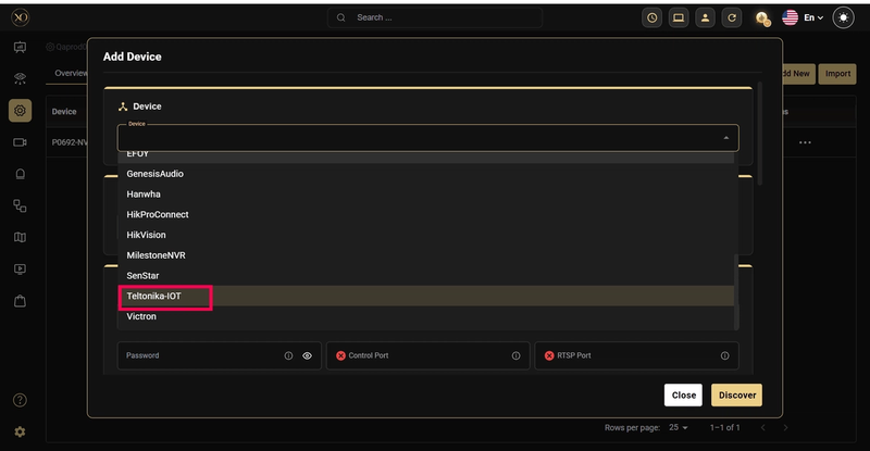
Step 3 — Select Device Type
In the device dialog, open the Device Type dropdown and select Teltonika IoT to load the appropriate configuration fields.
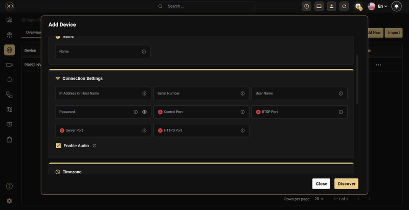
Step 4 — Enter Device Details
Fill in all required fields to establish a secure connection between GCXONE and the Teltonika router. Each field is described in detail below.
| Field | Description | Notes |
|---|---|---|
| Device Type | Select 'Teltonika IoT' from the dropdown | Must match exactly — determines which telemetry model is used |
| Device Name | A unique, descriptive name for this device in GCXONE | Use a naming convention that identifies the site and device, e.g., 'Tower-North-Router-01' |
| IP Address | Public or VPN-accessible IP address of the Teltonika router | Must be reachable from the GCXONE server; use VPN if the device is behind NAT |
| Serial Number | The hardware serial number printed on the router | Found on the device label or in the Teltonika device management portal |
| Control Port | HTTP port for device communication | Default is typically port 80; confirm with your network configuration |
| Username | Administrative login username for the router | Must have full access to all device parameters and APIs |
| Password | Administrative login password for the router | Stored securely within GCXONE; use a strong, unique password |
Step 5 — Save and Verify Connection
After entering all fields, click Save. GCXONE will immediately attempt to establish a connection with the Teltonika router using the provided credentials.
A successful connection results in:
- The device appearing in the site's device list with an active status indicator
- Live telemetry data beginning to flow into GCXONE (signal strength, network status, I/O states)
- The device becoming available for alarm rule configuration
If the connection fails, verify that the IP address is reachable, the port is open, and the credentials are correct. Check that no firewall rules are blocking GCXONE's access to the device
Alarm Rules Configuration
GCXONE uses a JSON-based alarm rule configuration to define which telemetry parameters are monitored, what thresholds trigger alerts, and how those alerts are identified in CMS integrations.
Alarm rules can be configured at the Site level or Device level. Teltonika connectivity rules are typically applied at the Device level for precision control.
How to Apply Alarm Rules
- Navigate to the target Site or Device in GCXONE.
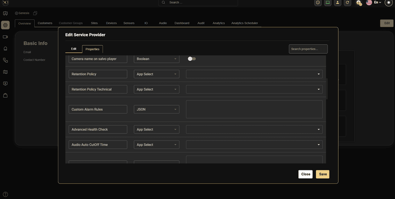
- Click Edit and go to the Additional Properties section.
- Locate the property named Custom Alarm Rules.
- Open the property's hamburger menu (⋮) and select Apply Default to load the preconfigured rule set. All rules are inactive by default.
- Modify the JSON to enable specific rules by setting "active": true for the relevant parameters.
- Set your thresholds, event codes, and group codes as needed.
- Click Save. GCXONE will immediately begin evaluating incoming telemetry against the configured rules.
By default, all alarm rules are inactive. You must explicitly set "active": true for each rule you want GCXONE to monitor. This prevents accidental alerts during initial setup.
Rule Structure
Each alarm rule follows a consistent JSON structure. Understanding the common fields helps when customizing rules:
| Field | Description |
|---|---|
| active | Boolean (true/false). Set to true to enable monitoring for this rule. When false, the rule is ignored. |
| eventCode | Unique string identifier used by GCXONE to communicate this alarm type to CMS integrations (IMMIX, Evalink, AmWin, LISA). This code appears in outbound alarm notifications. |
| groupCode | Logical grouping identifier for Tower Monitoring workflows. Used for filtering, organizing, and managing related alarms within GCXONE's Tower Alarm Manager. |
Event Codes are used for cross-system CMS notification (e.g., IMMIX, Evalink). Group Codes are GCXONE-internal identifiers for tower alarm workflows. Both must be present for full integration.
Teltonika Connectivity Alarm Rules
The following alarm rules are available for Teltonika IoT devices under the Connectivity Monitoring section of the Custom Alarm Rules JSON. Each rule monitors a specific aspect of network health, physical I/O, or security.
- Input/Output Status Change Rule
Monitors physical state changes on Teltonika I/O ports. This rule covers digital, analog, isolated, and relay inputs and outputs — essential for detecting door openings, power events, external sensor triggers, and equipment state changes.
Default JSON Configuration
"IOStatusChange": {
"input": {
"AnalogCurrentLoop": {"active": false, "low": 4, "high": 20},
"AnalogInput": {"active": false, "low": 11, "high": 14},
"DigitalInput": {"active": false, "ranges": ["Low level", "High level"],
"alertOn": "High Level"},
"IsolatedInput": {"active": false, "ranges": ["Low level", "High level"],
"alertOn": "High Level"},
"PowerSocketInput": {"active": false, "ranges": ["Low level", "High level"],
"alertOn": "High Level"},
"eventCode": "input.statechange",
"groupCode": "tower.input.statechange"
},
"output": {
"IsolatedOutput": {"active": false, "ranges": ["Low level", "High level"],
"alertOn": "High Level"},
"Relay": {"active": false, "ranges": ["open", "closed"], "alertOn": "open"},
"PowerSocketOutput": {"active": false, "ranges": ["Low level", "High level"],
"alertOn": "High Level"},
"eventCode": "output.statechange",
"groupCode": "tower.output.statechange"
}
}
Input Types
| Input Type | Description and Parameters |
|---|---|
| AnalogCurrentLoop | Monitors 4–20 mA current loop sensors. Set low/high to the acceptable current range. Alerts when current falls outside this range. |
| AnalogInput | Monitors analog voltage inputs (e.g., 11–14V). Set low/high thresholds. Alert triggers when voltage is out of range. |
| DigitalInput | Binary state monitoring. Set alertOn to the state that should trigger an alarm (e.g., 'High Level' for door open detection). |
| IsolatedInput | Electrically isolated digital input. Same configuration as DigitalInput. Used when isolation from the main circuit is required. |
| PowerSocketInput | Monitors power socket state (Low/High level). Set alertOn to the triggering state. Suitable for mains power detection. |
Output Types
| Output Type | Description and Parameters |
|---|---|
| IsolatedOutput | Monitors the state of an isolated output channel. Set alertOn to 'High Level' to alert when the output is active. |
| Relay | Tracks relay state (open/closed). Set alertOn to 'open' to alert when the relay is not energized. Useful for contactor or lock monitoring. |
| PowerSocketOutput | Monitors power socket output state. Alert when the output reaches the configured alertOn state. |
- SIM Card Data Package Usage Rule
Tracks monthly mobile data consumption for the Teltonika router's SIM card. Triggers a warning when data usage reaches the configured percentage of the total monthly allowance — preventing unexpected overage charges or service interruptions.
Default JSON Configuration
"simCardDataPackage": { "active": false, "simBillingStartDate": 1, "simDataPackageGB": 10, "usageWarningPercent": 80, "eventCode": "sim.data.usage.warning", "groupCode": "tower.connectivity.simdata.alert"}
Configuration Parameters
| Parameter Name | Description | Example Value |
|---|---|---|
| simBillingStartDate | Billing cycle start date of the SIM plan (currently inactive) | 1 |
| simDataPackageGB | Total mobile data allocated per month (in GB) | 10 |
| usageWarningPercent | Warning threshold as a percentage of total data usage | 80 |
| eventCode | CMS alarm identifier for this event type | sim.data.usage.warning |
| groupCode | Internal tower alarm group for filtering and routing | tower.connectivity.simdata.alert |
Example Behavior
- With simDataPackageGB set to 10 and usageWarningPercent set to 80, GCXONE triggers an alert when cumulative SIM data usage exceeds 8GB in the billing period.
- The alert clears automatically when data usage resets at the start of the new billing cycle.
- Adjust the threshold lower (e.g., 70%) for early warning on sites with limited connectivity alternatives.
- Cellular Network Loss Rule
Detects when the Teltonika router loses mobile network connectivity or the signal drops to an unacceptable level. Immediately alerts operators to potential site communication failures.
Default JSON Configuration
"cellNetworkLoss": {
"active": false,
"eventCode": "modem.signal.warning",
"groupCode": "tower.connectivity.signal.alert"
}
Example Behavior
- GCXONE triggers an alert when the cellular signal drops below the acceptable threshold or connectivity is lost entirely.
- The alert automatically clears once the signal returns to an acceptable level.
- This rule has no threshold parameters — it relies on GCXONE's built-in signal quality evaluation for the router's reported modem status.
- Geo-Fencing Rule
Monitors the GPS position of the Teltonika router relative to its assigned site location. Triggers an alert if the device moves beyond the configured radius — detecting potential tower displacement, theft, or unauthorized movement.
Default JSON Configuration
"geoFencing": {
"active": false,
"radiusMetersWarning": 500,
"eventCode": "geo.fence.breach",
"groupCode": "tower.connectivity.geofence.alert"
}
| Parameter Name | Description | Example Value |
|---|---|---|
| radiusMetersWarning | Radius (in meters) from the defined geo-fence center (typically, the site's geo location) within which the tower must remain | 500 |
| eventCode | CMS alarm identifier for geo-fence breach events | geo.fence.breach |
| groupCode | Internal tower alarm group identifier | tower.connectivity.geofence.alert |
Example Behavior
- The geo-fence boundary is centered on the coordinates defined in the parent Site's configuration in GCXONE.
- If the GPS position reported by the Teltonika router exceeds 500 meters from the site center, a breach alert is generated.
- The alert clears automatically when the device returns within the defined boundary.
- Reduce the radius for permanent fixed installations; use a larger radius for mobile or semi-mobile tower deployments.
- Jammer Detection Rule
Detects potential radio frequency jamming attempts based on sudden signal degradation and poor Reference Signal Received Quality (RSRQ). Jammer detection is critical for security-sensitive tower deployments where signal interference may indicate deliberate disruption attempts.
Default JSON Configuration
"jammerDetection": {
"active": false,
"criteria": {
"signalDropThreshold": 25,
"minSignalLevel": -113,
"rsrqThreshold": -20
},
"eventCode": "modem.jammer.detected",
"groupCode": "tower.connectivity.jamming.alert"
}
``
| Parameter Name | Description | Example Value |
|---|---|---|
| signalDropThreshold | Percentage drop in signal strength considered as a potential jamming event | 25 |
| minSignalLevel | Minimum acceptable signal level (in dBm); if signal goes below this, jamming is suspected | -113 |
| rsrqThreshold | Minimum acceptable RSRQ (Reference Signal Received Quality); poor RSRQ may indicate interference | -20 |
| eventCode | CMS identifier for jammer detection events | modem.jammer.detected |
| groupCode | Tower alarm group identifier | tower.connectivity.jamming.alert |
Example Behavior
- GCXONE evaluates both absolute signal level (RSRQ) and the rate of signal change (drop percentage) to distinguish genuine jamming from normal signal variation.
- An alert is triggered when the signal drop exceeds 25% OR the RSRQ falls below -20 and signal level is below -113 dBm simultaneously.
- The alert clears automatically once normal signal stability is restored.
Jammer detection thresholds may need tuning based on local RF environment conditions. Sites in urban areas with natural signal variation may require a higher signalDropThreshold to reduce false positives.
Configuration Reference
a. Complete Teltonika Connectivity Alarm Rules JSON
The following is the complete default JSON configuration for all Teltonika connectivity alarm rules. Copy this into the Custom Alarm Rules property and modify as needed for your deployment.
"connectivityMonitoring": {
"IOStatusChange": {
"input": {
"AnalogCurrentLoop": {"active": false, "low": 4, "high": 20},
"AnalogInput": {"active": false, "low": 11, "high": 14},
"DigitalInput": {"active": false, "ranges": ["Low level", "High level"],
"alertOn": "High Level"},
"IsolatedInput": {"active": false, "ranges": ["Low level", "High level"],
"alertOn": "High Level"},
"PowerSocketInput": {"active": false, "ranges": ["Low level", "High level"],
"alertOn": "High Level"},
"eventCode": "input.statechange",
"groupCode": "tower.input.statechange"
},
"output": {
"IsolatedOutput": {"active": false, "ranges": ["Low level", "High level"],
"alertOn": "High Level"},
"Relay": {"active": false, "ranges": ["open", "closed"], "alertOn": "open"},
"PowerSocketOutput": {"active": false, "ranges": ["Low level", "High level"],
"alertOn": "High Level"},
"eventCode": "output.statechange",
"groupCode": "tower.output.statechange"
}
},
"simCardDataPackage": {
"active": false,
"simBillingStartDate": 1,
"simDataPackageGB": 10,
"usageWarningPercent": 80,
"eventCode": "sim.data.usage.warning",
"groupCode": "tower.connectivity.simdata.alert"
},
"cellNetworkLoss": {
"active": false,
"eventCode": "modem.signal.warning",
"groupCode": "tower.connectivity.signal.alert"
},
"geoFencing": {
"active": false,
"radiusMetersWarning": 500,
"eventCode": "geo.fence.breach",
"groupCode": "tower.connectivity.geofence.alert"
},
"jammerDetection": {
"active": false,
"criteria": {
"signalDropThreshold": 25,
"minSignalLevel": -113,
"rsrqThreshold": -20
},
"eventCode": "modem.jammer.detected",
"groupCode": "tower.connectivity.jamming.alert"
}
}
``
b. Event Codes and Group Codes Summary
Quick reference for all Teltonika connectivity event codes and group codes:
| Rule | Event Code | Group Code |
|---|---|---|
| I/O Input State Change | input.statechange | tower.input.statechange |
| I/O Output State Change | output.statechange | tower.output.statechange |
| SIM Data Usage Warning | sim.data.usage.warning | tower.connectivity.simdata.alert |
| Cellular Network Loss | modem.signal.warning | tower.connectivity.signal.alert |
| Geo-Fence Breach | geo.fence.breach | tower.connectivity.geofence.alert |
| Jammer Detection | modem.jammer.detected | tower.connectivity.jamming.alert |
c. Configuration Best Practices
- Always start with Apply Default to load the complete preconfigured rule set before making changes.
- Enable rules incrementally — start with critical rules (network loss, jammer detection) before enabling threshold-sensitive rules like I/O state changes.
- Test alarm rules in a staging environment or on a single device before deploying to all sites.
- Set usageWarningPercent for SIM data at 70–80% to give operators enough time to take action before the plan is exhausted.
- For geo-fencing on permanent sites, use a small radius (100–200m). For temporary deployments, use 500m or more.
- Document your event codes and group codes in your CMS configuration to ensure correct alarm routing.
OpenVPN Configuration on Teltonika Router
From the NXGEN side, we will provide you with an OpenVPN (ovpn) configuration file and a LAN IP segment that needs to be assigned to the customer network.
Step-by-Step Configuration
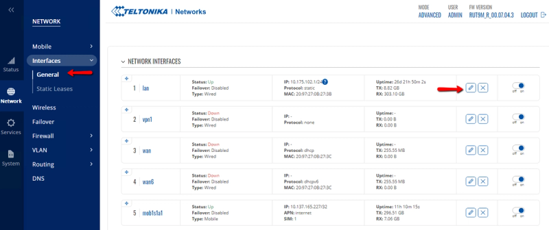
1. Change the Default LAN IP of the Teltonika Router to the IP provided by the NXGEN Team
- Open the router web console.
- Navigate to Network -> Interfaces -> General -> Edit LAN.
- Enter the LAN IP and Subnet -> Save.
2. Import the OpenVPN Configuration File to the Router Provided by the NXGEN Team
-
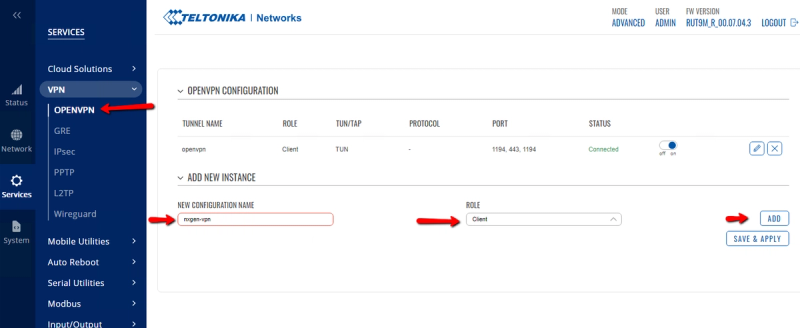
On the web console, navigate to Services -> VPN -> OPENVPN.
-
Under the Add New Interface option, provide the "VPN Name" and set the Role to "Client" -> Add.
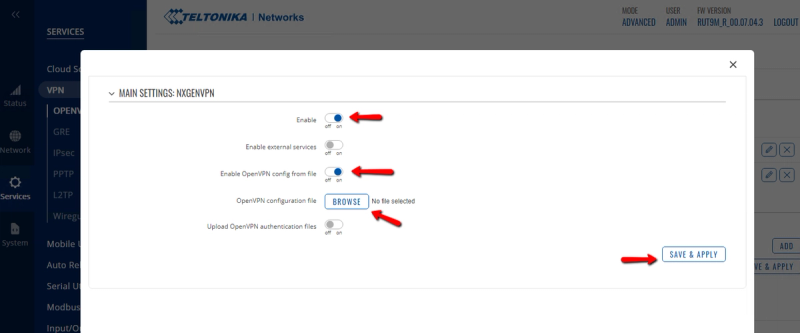
-
Select "Enable OpenVPN configuration file" -> Browse and attach the ovpn file.
-
Select Enable and Save.
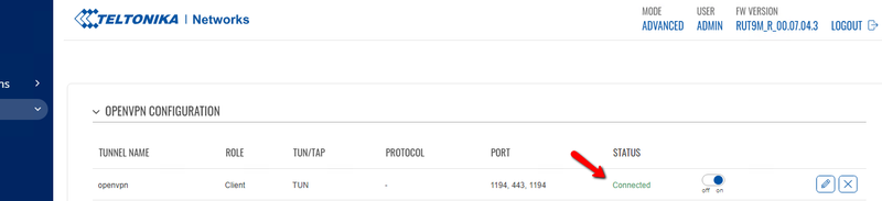
-
After a couple of minutes, the status will change to "Connected".
3. To Test the Connectivity:
-
Navigate to System -> Administration -> Troubleshoot.
-
Under Diagnostics, select the method "Ping" -> Enter IP "10.10.22.42" -> Perform.
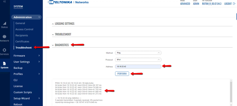
-
The VPN connection is successfully configured if you get a successful ping response.
Troubleshooting
Device Won't Connect
| Symptom / Check | Resolution |
|---|---|
| Connection fails immediately after Save | Verify the IP address is reachable from the GCXONE server. Try pinging the IP from the server or checking VPN connectivity. |
| Authentication error | Confirm the username and password are correct and have administrative access. Log in directly to the Teltonika admin interface to verify credentials. |
| Port-related connection failure | Check that the configured Control Port is correct and not blocked by a firewall. Default is port 80. |
| Device shows offline after initial connection | Check whether the Teltonika router's IP address has changed (DHCP). Consider using a static IP or DHCP reservation. |
Alarm Rules Not Triggering
| Symptom / Check | Resolution |
|---|---|
| No alerts received for a breached threshold | Verify the rule has "active": true in the JSON. Check that the Custom Alarm Rules JSON is valid (no syntax errors). |
| eventCode not appearing in CMS | Confirm the event code is configured in your CMS integration. Check the CMS channel mapping in GCXONE under the site's integration settings. |
| False positive alerts (too many alerts) | Adjust thresholds. For analog inputs, widen the low/high range. For jammer detection, increase signalDropThreshold. |
| Geo-fence alerts for a fixed site | Verify the site's GPS coordinates in GCXONE are correctly set to the actual tower location. Increase radiusMetersWarning if GPS reporting has variance. |
SIM Data Rule Not Activating
- Ensure the Teltonika router is reporting SIM data usage metrics to GCXONE.
- Verify that simDataPackageGB matches your actual SIM plan size.
- The simBillingStartDate field is currently inactive — data usage tracking uses the calendar month for now.
For additional support, contact your NXGEN representative or refer to the full GCXONE Tower Monitoring Configuration Guide which covers Victron Energy and EFOY Fuel Cell monitoring in addition to Teltonika IoT connectivity.